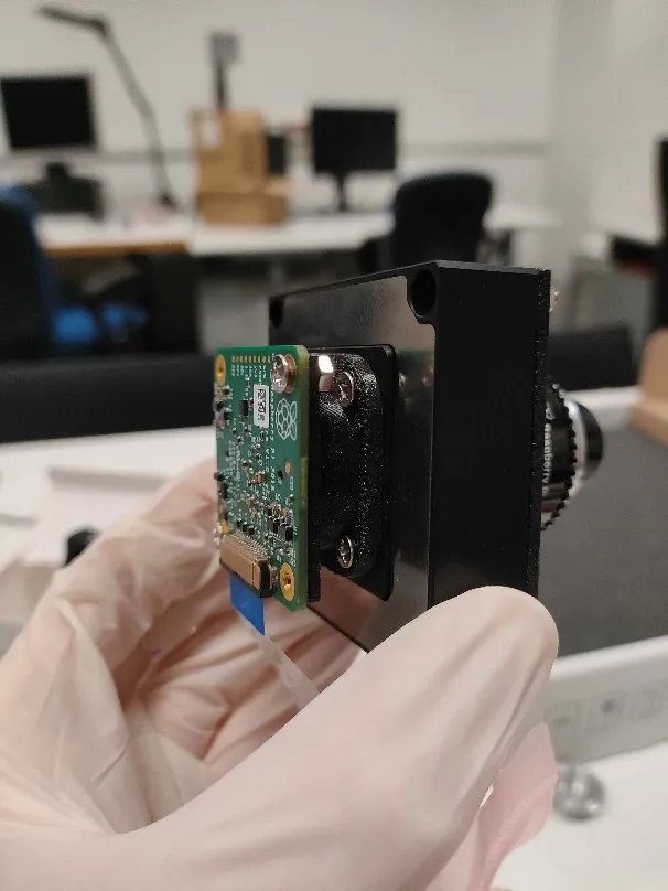
Earth-observation satellites in very low Earth orbit (around 250 km, Sun-synchronous) move fast relative to the ground, so the scene sweeps across the image sensor during exposure and blurs it. Forward motion compensation cancels this apparent motion during acquisition. In the system I am developing, the sensor, rather than the optics, is translated on a two-axis piezo stage in counter-phase with the scene, following a sinusoidal profile; the image is captured during the forward-scan half-wave.
This is ongoing work within the Space It Up! project (ASI and MUR), Spoke 1, work package WP1.2, a University of Bologna task led with Prof. Dario Modenini. I am handling procurement, opto-mechanical integration, electronics, and control.
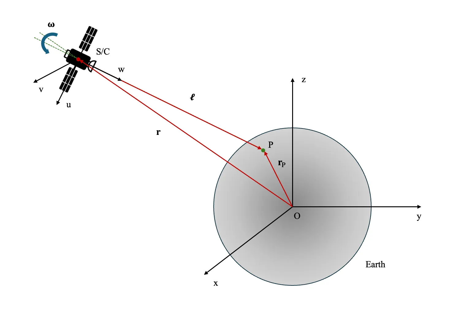
Two concepts of operation were studied:
- Model-based: the line-of-sight motion is predicted from an analytical model of the orbit and attitude, and the stage follows the computed profile.
- Image-in-the-loop: the motion is measured directly from pairs of short-exposure frames using phase-correlation optical flow.
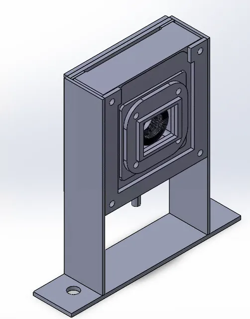
The sensor sits on a PI P-612.2SL piezo XY stage with 100 x 100 µm travel (about 20 pixels) and 10 nm repeatability, driven closed-loop through its capacitive sensor by a PI E-610.S0 controller and an NI USB-6221 DAQ. The control software is written in Python (nidaqmx). The opto-mechanics are custom: a threaded M12 flange and 3D-printed parts, with the Sony IMX249 sensor removed from its original board and remounted on the moving stage.
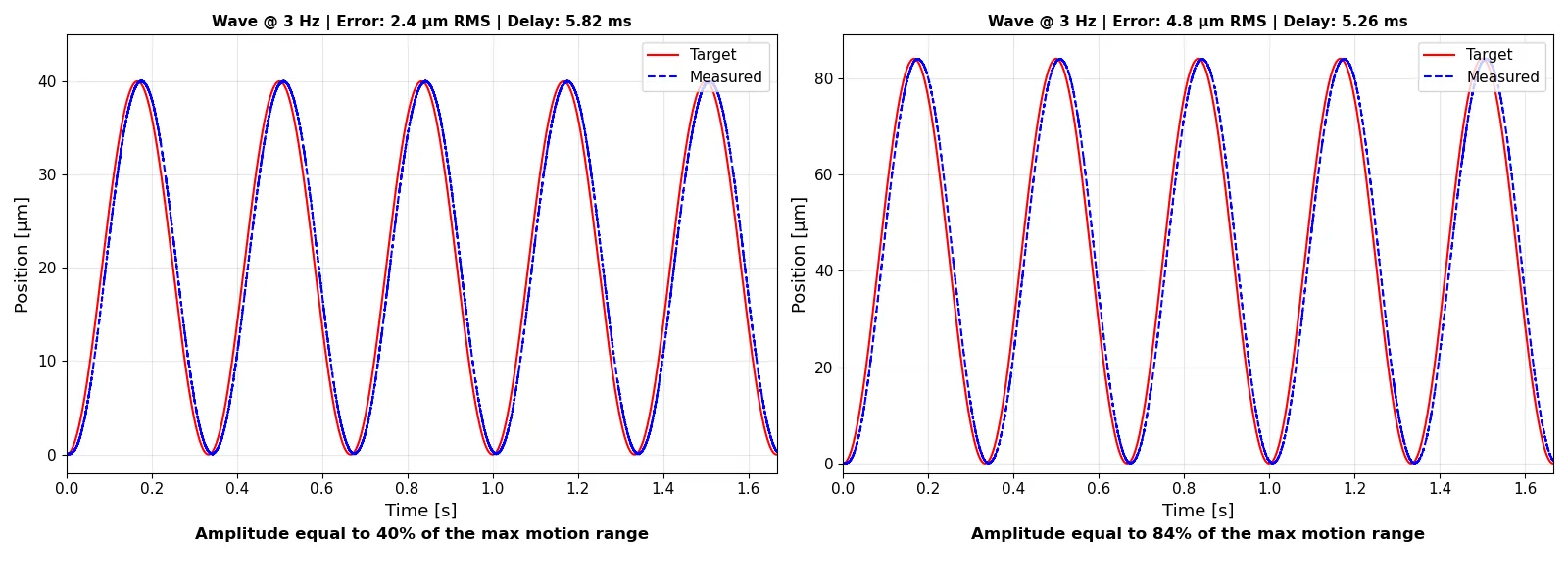
The stage tracks a 3 Hz sinusoidal reference with an error of 2.5 to 5 µm RMS and a lag of about 5 ms. In simulation, the compensation lets the integration time be extended up to five times while keeping image smear below one pixel.