Team members: Alessandro Lotti, Dario Modenini, Paolo Tortora.
Deep-learning pose estimation trained on synthetic images tends to lose accuracy on real images, and collecting labelled real images of spacecraft is hard. I designed and commissioned a hardware-in-the-loop testbed that reproduces the relative motion between a camera and a target satellite under solar-spectrum illumination, so that real, accurately labelled images can be produced in the laboratory. The testbed is the subject of a chapter of my PhD thesis and was presented at the 10th CEAS Aerospace Europe Conference (Turin, December 2025). The work is part of the Space It Up! project, funded by the Italian Space Agency (ASI) and the Italian Ministry of University and Research (MUR) under contract No. 2024-5-E.0.
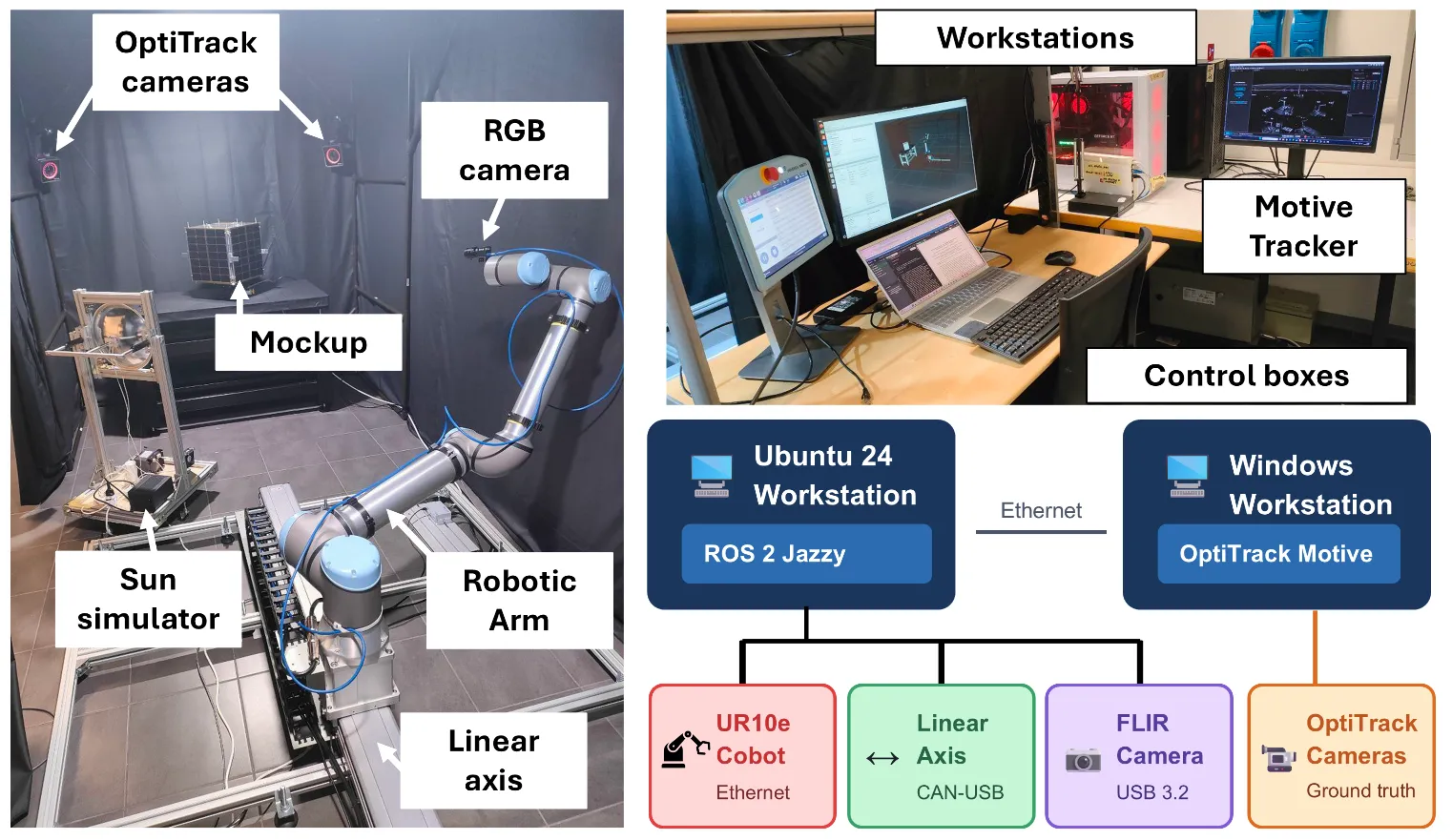
The facility is built around a UR10e collaborative robot (6 degrees of freedom, 1.3 m reach, 12.5 kg payload) mounted on a motorised Ewellix linear axis (1.8 m stroke), for seven degrees of freedom in total. An optical table holds an engineering model of the ALMASat microsatellite (33 x 33 x 31.5 cm) as the target mock-up. The main hardware:
- Custom Sun simulator: a 400 W metal halide (HMI) bulb with a 12-inch parabolic reflector, reaching an irradiance of about 1200 W/m².
- RGB camera: a FLIR machine-vision camera (1920 x 1200 px, 8 mm lens) mounted on the end-effector. The configuration can be inverted, fixing the camera and moving the satellite on the arm to simulate more complex relative dynamics.
- Ground truth: four OptiTrack PrimeX 22 motion-capture cameras.
- A dark room of 4.4 x 2.0 x 2.2 m for control over lighting, a uniform background, and safety against the Sun simulator light.
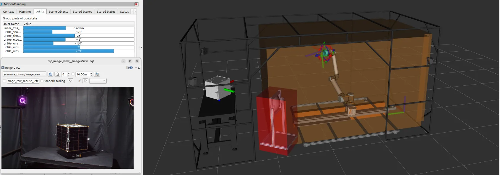
The software stack runs on ROS 2 (Jazzy) with MoveIt 2 for motion planning, using three planning groups for the arm, the linear axis, and the joint 7-DoF system. The UR cobot integrates through its standard driver, while the linear axis required a custom implementation: a dedicated ROS node bridges its CANopen (CiA 402) interface to the FollowJointTrajectory action expected by MoveIt. Switching the drive to Cyclic Synchronous Velocity mode and tuning its gains improved synchronisation and reduced vibration, so the rail can follow MoveIt trajectories at varying speed.
To recover accurate camera-target poses, I implemented automated calibration scripts: camera intrinsics, hand-eye calibration (solving the AX = XB problem between end-effector and camera), and mock-up pose calibration in the world frame via PnP.
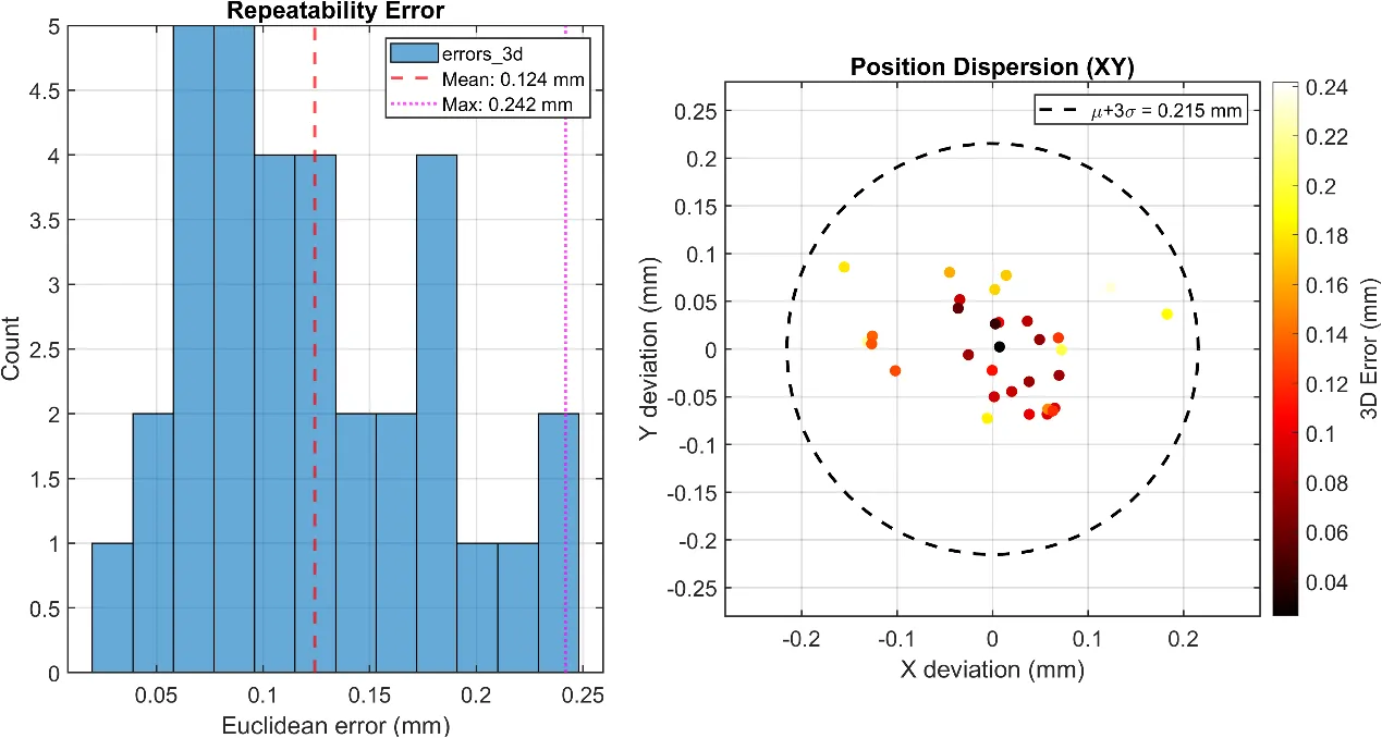
I characterised the system by moving it to random joint configurations and back to a reference pose, recording the end-effector marker with the OptiTrack cameras as ground truth. Across 33 valid trials in a workspace of about 1.5 x 0.6 x 2.0 m, the mean Euclidean error was 0.124 mm, with a maximum of 0.242 mm, close to the intrinsic accuracy of the motion-capture system itself.
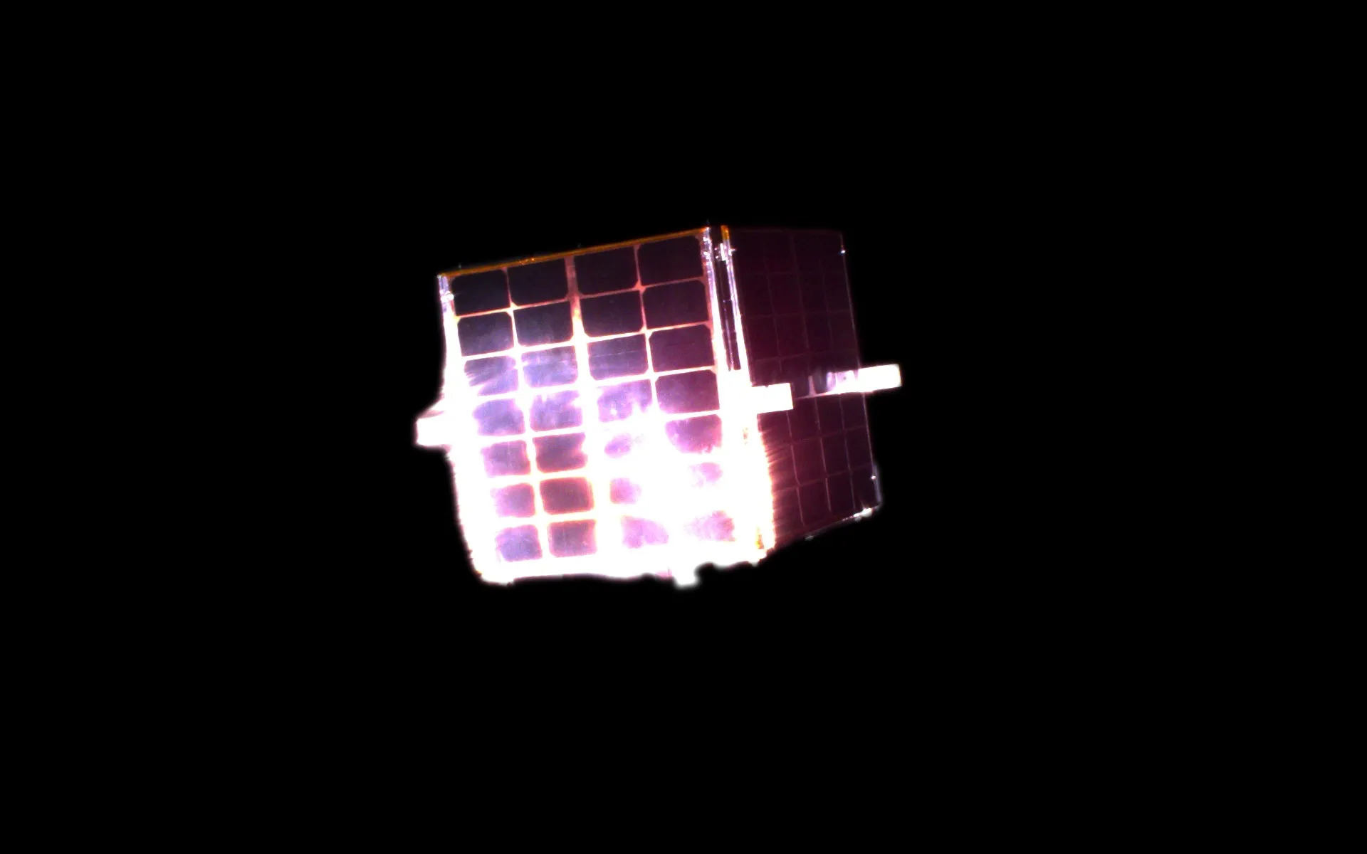
Images of the mock-up are captured automatically, with the corresponding pose queried from the ROS transform tree after each movement, and the background removed with Segment Anything. Paired with synthetic images rendered in Blender Cycles, these data are meant to support the training, validation, and testing of pose estimation pipelines. The testbed is operational; running the pose estimation algorithms on it is planned future work. A PI rotary stage has since been added to simulate single-axis spin, which will bring the system to eight degrees of freedom once integrated into ROS.