Team members: Andrea Curatolo, Dario Modenini, Giacomo Curzi, Alessandro Lotti, Daniele Pecorella, Eliseo Strollo, Alfredo Locarini.
The NanoDyna ADCS facility, currently under development by the University of Bologna and NautiluS - Navigation in Space, with coordination and funding from ESA, is designed for testing nanosatellites' attitude determination and control systems. The facility, set to be installed at ESTEC, will facilitate the verification of closed-loop attitude control through physical sensor stimuli. Testing nanosatellites in such an environment is anticipated to uncover issues not identified during the compressed verification campaigns typical of the New-Space approach.
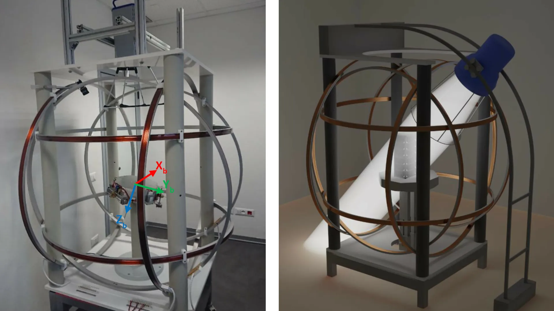
The project's development is split into two primary pillars: the Air Bearing Table (ABT) development and the Physical Stimulus (PS) development. The facility will incorporate various external physical stimuli, including a Helmholtz cage to emulate the magnetic field and a sun simulator. Additionally, a ground truth system will be integrated.
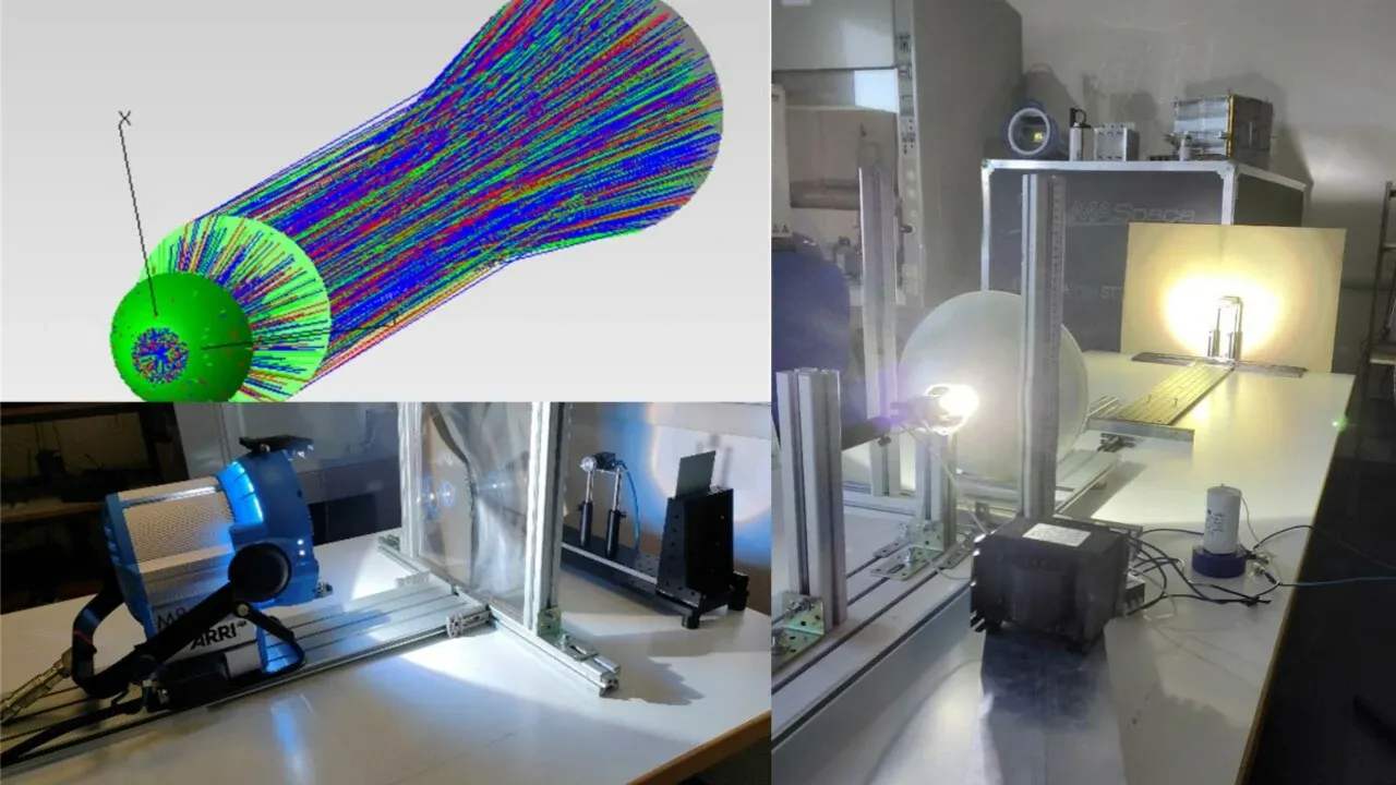
My role in this project involves the design and testing of sun simulator solutions. Throughout the project, I have enhanced my understanding of optics and acquired proficiency in utilizing optical ray-tracing software.
For more details on the sun simulator, refer to the information provided below.
The facility shall include a sun lamp with the following properties:
- Angular divergence ≈ 0.53°.
- Spatial non-uniformity < 10%.
- Illumination working diameter ≥ 34 cm.
- Spectral content and intensity aimed at stimulating photodiode or photocell sensors at near 1 solar constant at 1 AU.
Ellipsoidal reflectors exhibit the capability to focus light from the first to the second focal point, making them efficient for light collection. However, achieving collimation necessitates the use of a Fresnel lens, and its focal point must align with the second focus of the reflector, leading to increased bulk. Moreover, the concentrated light can reach irradiance levels comparable to several suns, presenting potential hazards for operators and imposing significant thermal stresses on the optics.
Parabolic reflectors were considered for their ability to collimate light with simpler mechanical and optical configurations. Considering the non-uniformity of the irradiance profile, large neutral density filter sheets were proposed to dissipate excess irradiance, offering flexibility in tuning configurations based on actual measurements.
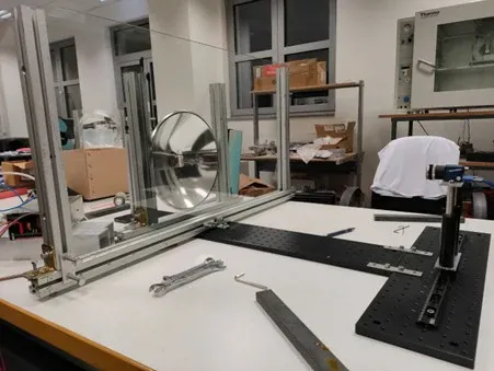
A test campaign was carried out using a smaller, cost-effective parabolic reflector from Edmund Optics to reduce uncertainties in the ray-tracing simulation. The major source of uncertainty in this kind of simulations is the model of the light source. Metal halide lamps emit volumetrically, and as manufacturers do not provide irradiance data, an optical model proposed in [1] was adopted to emulate volumetric emissivity. The bulb was represented as a set of 11 concentric elliptic shells, with the sum of power levels reaching 80% of the bulb's rated power to account for efficiency.
Power distribution along the emission spectrum was accomplished using weights calculated based on a 6000K blackbody. The glass was integrated into the simulation as an absorbing surface with a transmission rate of 0.79. The target area was modeled as a circle with a diameter of 34 cm, exhibiting 100% absorption in the range 400-1100 nm and 0 absorption outside this range to simulate the light meter response.
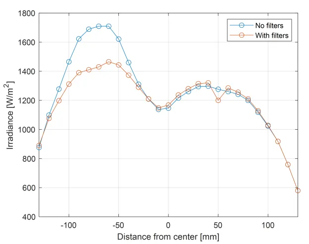
To achieve light uniformity, our proposed solution involves attaching ND filter sheets to the front panel. The provided figure illustrates a comparison of irradiance with and without the use of filters, showcasing increased uniformity in the former case. This configuration, involving a metal halide lamp placed at the focus of a parabolic reflector with optical filters in front, identifies the optimal setup to achieve the highest degree of compliance with the specified requirements.
[1] J. P. Roba and N. P. Siegel, ‘The design of metal halide-based high flux solar simulators: Optical model development and empirical validation', Solar Energy, vol. 157, pp. 818–826, Nov. 2017.DOI.